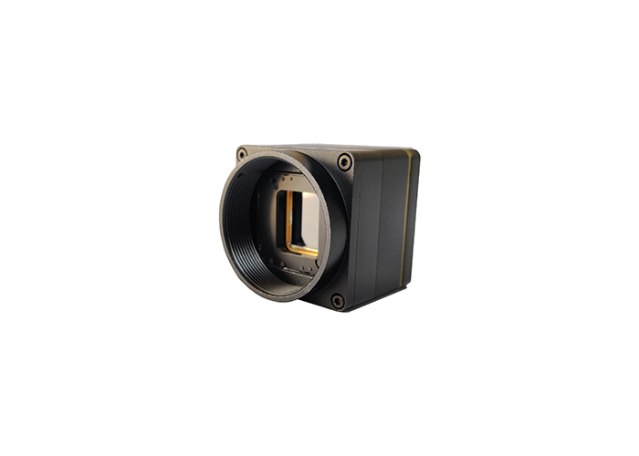
A3817T13 Temperature Measuring Body Infrared Thermal Camera Module
Part 1. Technical index
Form 1 Technical index of network temperature measuring movement
| Detector |
| Detector type | LWIR uncooled focal plane array |
| Resolution | 384x288/640x480 |
| Pixel size | 17μm |
| NETD | <50mk@300K, f1.0 |
| Image frame rate | 50Hz/25Hz |
| Spectral range | 8-14μm |
| Video display processing |
| Non-uniform correction | Baffle |
| Video output | CCIR / PAL composite video (50Hz) |
| Image polarity | Black heat/White heat/Brown/Red heat/Iron red/Rainbow |
| Digital zoom | Follow-up support |
| Brightness | Adjustable |
| Contrast | Adjustable |
| Boot time | <5s |
| Lens | 13mm/19,25mm |
| Interface for thermal imaging movement |
| Data interface | RJ45(100M Ethernet) |
| Communication control | UART/RS232 LVCMOS 2.5V-3.3V compatible |
| Analog video output | CVBS |
| Digital video | H264 video streaming, support Onvif V2.4 |
| Alarm | GPIO |
| Temperature measurement function |
| Range of TEMP measurement | 26℃~46℃ |
| Accuracy of TEMP measurement | ±0.2℃(Reference black body), ±0.3℃(Single machine work) |
| Distance of TEMP measurement | <8m |
| Alarm | Support area alarm, support isothermal analysis |
| Secondary development support | Secondary correction, read out part of the spot temperature, read
out part of the block temperature |
| Power supply |
| Range of Voltage | 9-12V |
| Power consumption | <2.5W |
| Environmental parameters |
| Operating time | 0℃~+30℃ |
| Range of storage TEMP | -45℃~+65℃ |
| Physical |
| Weight(without lens) | <40g |
| Size(mm) | 38x38x35(without lens interface) |
Part 2. Interface definition
1.Interface board socket diagram
2.Socket description
(1) RS485(Ports ofRS485)
| Pin number | Definition |
| 1 | Signal ground |
| 2 | RS485_A(RS485+) |
| 3 | RS485_B(RS485-) |
(2) CVBS(Analog video output)
| Pin number | Definition |
| 1 | VIDEO(Video+) |
| 2 | GND(Video-) |
(3) PWRIN(Power input)
| Pin number | Definition |
| 1 | 12V Power input |
| 2 | Power ground |
| 3 | |
| 4 | Power ground |
(4) SD Expansion
| PIN number | Definition |
| 1 | Output 12V |
| 2 | GND |
| 3 | USB_PWREN |
| 4 | USB_DP |
| 5 | USB_DM |
| 6 | GND |
| 7 | SDIO_CARD_PWREN |
| 8 | SDIO_CDATA2 |
| 9 | SDIO_CDATA3 |
| 10 | SDIO_CDATA1 |
| 11 | SDIO_CDATA0 |
| 12 | SDIO_CCMD |
| 13 | SDIO_CCLK_OUT |
| 14 | GND |
| 15 | UART_TXD |
| 16 | UART_RXD |
Note:Logic frequency 3.3V
(5) UART
| Pin number | Definition |
| 1 | UART2_TX |
| 2 | UART2_RX |
| 3 | UART3_TX |
| 4 | UART3_RX |
| 5 | GPIO(Alarm I/O) |
| 6 | GND |
Note:
1.UART2_TX, UART2_RX, UART3_TX, UART3_RX, GPIO are the direct
output of FPGA, and the level is 2.5V LVCMOS.
2.UART2 can work and is used to communicate directly with the
thermal imaging core; UART3 is used to expand external devices,
such as LRF, which currently has no function.
3.The signal defaults to a low level, and when the level is high,
it is in an alarm state.
(6) MOTER2(Motor drive and feedback)
| Pin number | Definition |
| 1 | OUT1(Motor drive output 1) |
| 2 | OUT2(Motor drive output 2) |
| 3 | GND |
| 4 | 4.5V Output |
| 5 | FBIN(Motor feedback input) |
(7) EUHERNET(Network Interface)
| Pin number | Definition |
| 1 | ACT |
| 2 | RJ1 |
| 3 | RJ2 |
| 4 | LINK |
| 5 | RJ3 |
| 6 | RJ6 |
Note: Logic level is 3.3V
(8) MOTER1(Motor drive and feedback)
| Pin number | Definition |
| 1 | OUT1(Motor drive output 1) |
| 2 | OUT2(Motor drive output 2) |
| 3 | GND |
| 4 | 4.5V Output |
| 5 | FBIN(Motor feedback input) |
(9) Alarm I/O
| Pin number | Definition |
| 1 | Alarm Outpt(5V Logic) |
| 2 | GND |
Note:The signal defaults to a low level, it will in an alarm state
when the level is high.
Part 3. Control protocol
1. The built-in web config of the movement can access the web
through IP to configure the movement. Basic functions of security
are provided by the machine; SD card storage is optional.
2. The menu of thermal imaging movement can be called through the
web to control the unique parameters of thermal imaging.


